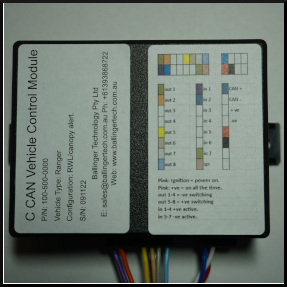
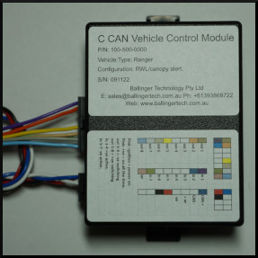
Run While Locked C CAN CAN Bus interface
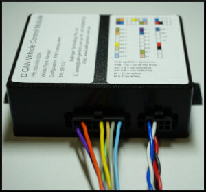 “Run While Locked” with the C CAN CAN Bus interface and control module.
C CAN+ can be configured for run while locked on most vehicles. It includes a unique key learn function for vehicles that will not allow the standard key fob RF module to lock the vehicle with the engine running eliminating the need for secondary key fobs and RF receiver/transmitters.
Standard features include:
- Accelerator pedal movement detect.
- Brake pedal movement detect.
- Hand brake on.
- Reverse gear detect.
- On switch input (momentary or latching)
- Flashing output for on indication.
- RWL start timeout to let you out of the vehicle.
With C CANs ability to be tailored for different applications Run While Locked can be combined with other functions like “High Beam detect” for driving light control, “Park brake off with canopy doors open” for an alert output, all from the one unit.
C CAN’s features are configurable by uploading a configuration file via its onboard serial port. Combined with an inbuilt CAN Bus sniffer this makes interfacing to new vehicles a simple process.
For customers wanting to tailor the module, we offer online support. This includes real time analysis of CAN Data, formulating a configuration file to suit your application, load and test. This service eliminates vehicle compatibility issues other manufacturers have and reduces turnaround times on new designs.
| Dual read only CAN Bus Interface monitoring up to 7 different CAN Bus functions. |
| User programmable interface for vehicle type ending vehicle compatibility issues. ie: Module is not locked to one vehicle type, but can be interfaced to most CAN Bus systems simply by searching that CAN Bus for the CAN Data string required and writing that into the modules Configuration file. |
| CAN Bus speed to VSS pulse out standard on all modules. |
| Can Bus analysis is carried out on up to 4 byte numbers (8, 16, 24 or 32 bits) using: Equal to. Greater than. Less than. |
| Adjustable quality and debounce timing for CAN inputs. |
| 7 switch inputs for interfacing to vehicle systems or control switches. |
| Switch inputs can be configured to work with momentary or latching. |
| Adjustable debounce timing for switch inputs. |
| 2 forms of serial input: RS232 and 5 - 12V DC serial. |
| 4 +VE switching outputs. 4 -VE switching outputs. 2 High current relay outputs. (HC Version only.) |
| Create a multifunction control module controlling multiple peripherals in the vehicle using any of the outputs independent of each other. ie: Output 1 = VSS (Speed out). Output 2 flashing when the control switch at input 1 is on eg. for an LED indicator showing system status. Output 3 = Park Brake on. (Canopy door alert.) Outputs 4-6 combined = Ignition control. Run while locked. Output 7 = High beam on. Driving light control. Output 8 = brakes, park brake and accelerator pedal for antitheft. |
| Control outputs independent of each other with a logical output equation. AND, OR, NAND, NOR and invert 1-4 inputs to switch an output on or off. ie: Input 1 & Input 3 & Input 7 & Input 8 = output 2. Output 2 is on if all inputs = on. Output 2 is off if any input is = off. |
| Combine output functions for applications that require more than one output to activate them ie: Run While Locked. |
| Flash Output function for applications that require outputs to flash on or off. Time base is adjustable. |
| Alternate flash function for applications that require outputs to flash in an alternating pattern with each other ie: one off and another on. Timebase is adjustable. |
| Pulse output momentarily on all outputs. Time base is adjustable. |
| Inbuilt LED indicators to show: - Power. - CAN Bus connected. - Output state for each output. - CAN Bus state for each CAN Bus input being analysed. - Switch input state for each switch connected. |
| Inbuilt CAN Bus sniffer eliminating the need for expensive CAN Bus analysers. |
| Reconfigurable by Configuration file. |
| Can Bus interfaces | C CAN: 1 interface. C CAN+: 2 interfaces. Both are read only ie: Passive. |
| CAN Bus standards compatibility | Standard CAN Standard CAN extended addressing. CAN FD CAN FD extended addressing. |
| Can Bus strings monitored: | Up to 7. |
| Switched inputs: | 7 Switched inputs configurable as: - 7 positive in active. or - 4 +ve in active. - 3 -ve in active. |
| Serial interface: | RS 232 full duplex. 5 - 12V serial in only. |
| Output Fets: | 4 positive switching. 4 negative switching. |
| Output relays: | 2 relays with access to normally open, normally closed and common relay terminals. ** |
| Output current | Fets: 4 Amps per output. Relays: 25 Amps each. ** |
| Interface logic | AND, OR, NAND or NOR up to 4 inputs for each output. |
| Voltage monitoring: | 9 V to 16 Volts. 12V systems. 19V to 30V. 24V systems. Available on all outputs. |
| Flash output function | Available on all outputs |
| Alternately flash output function. | Available on all outputs |
| Combine outputs function. | Available on all outputs. |
| Momentary output function. | Available on all outputs |
| Voltage | 12V * 24V on request. * |
| Current | 55 ma running. * Sleep mode current dependent on functions active in sleep. |
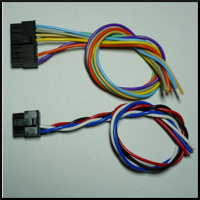
| Connector System | 1 X Molex Microfit connectors 1 X Molex Minifit Jnr connector 1 X Molex MegaFit connector. (HC version only) |
| Operating Temperature | -20C to 80C |
| Storage Temperature | -40C to +100C |
| Weight | 100g |
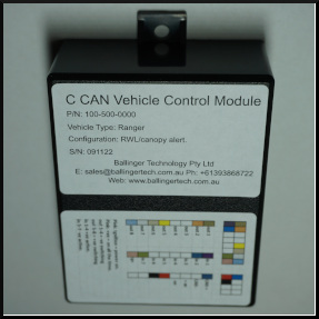
| Dimensions | H 33 mm x W 70 mm x L 88mm |
| Housing Material | ABS |
| * Nominal value only. | |
| ** HC Versions only. |
| Features | C CAN 100-500-000 | C CAN HC 100-501-000 | C CAN+ 100-502-000 | C CAN+ HC 100-503-000 |
| Can Bus interfaces | 1 | 1 | 2 | 2 |
| Can Bus strings monitored: | 7 | 7 | 7 | 7 |
| Switch inputs: | 4 | 4 | 7 | 7 |
| Serial interface: | 1 | 1 | 2 | 2 |
| Output Fets: | 4 | 4 | 8 | 8 |
| Output relays: | 0 | 2 | 0 | 2 |
| Interface logic | Yes | Yes | Yes | Yes |
| Voltage monitoring: | Yes | Yes | Yes | Yes |
| Flash output function | Yes | Yes | Yes | Yes |
| Alternately flash output function. | Yes | Yes | Yes | Yes |
| Combine outputs function. | Yes | Yes | Yes | Yes |
| Momentary output function. | Yes | Yes | Yes | Yes |
| Config file | Yes | Yes | Yes | Yes |
|